Design Refinements
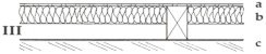
Figure 18. Tuned resonant sound absorbers, showing three possible ways to mount the absorptive material in the airspace.
Is there any way to decide which of these three treatments (or, perhaps, some other variant) will yield the maximum amount of absorption at that frequency?
And is there any especially effective way of disposing the various elements of the resonant absorber to maximize the absorption?
Once the choice of resonance frequency is made, the actual absorption characteristics can be changed according to the choice of the absorptive material in the cavity and also where the material is located in the cavity , as shown in the sketch of Figure 18,
In each case, a is the perforated sheet, b is the sound absorptive material and c is a rigid backing, such as a wall.
The sound absorptive behavior for these three conditions is shown in Figure 19. The curve with the open circles represents Condition I; that with the filled circles, Condition II; and that with the x's, Condition III.
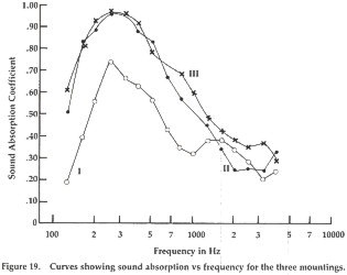
Obviously, the most effective arrangement is that with the fibrous material located near the perforated sheet. The worst condition is with the absorptive material close to the wall.

